 D.I.Y
RC TRAINER
D.I.Y
RC TRAINER backD.I.Y
RC TRAINER
| I
am not a newbee to aeromodelling. Has made quite a number of models during
college days as an NCC cadet of 1 kerala air sqn NCC - from 1979 - 1984.
After a long break of almost 20 years i started again during 2005. The RC
model trainer project was infact my second model after completion of my
control line model a peace maker from a kit.
|
 |
See the pictures below for a better idea regarding the construction of the model.
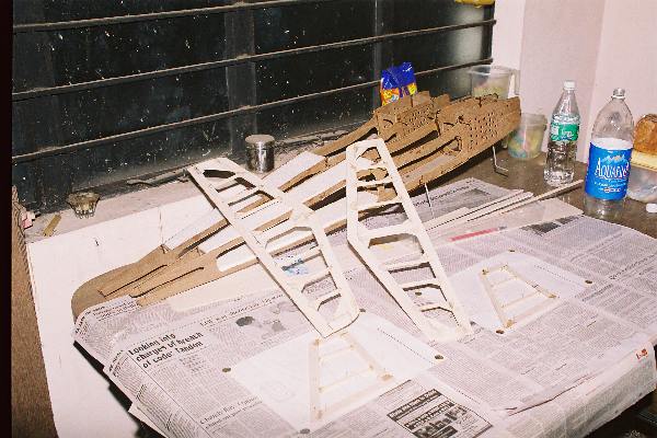 |
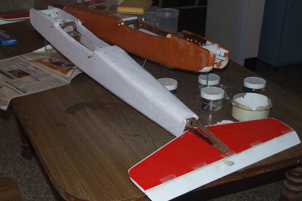
One of the first pictures taken. tailplane and fins made of balsa is visible |
 |
The fuselage cutout from 2 mm ply with a jig saw cutter. maximum effort has gone into reducing the weight. a ply of 1 mm is better but not avilable in kerala so i had to go for 2mm. Fin and tail are balsa. notice the foam inserts on the top and bottom of the fuselage for strength. |
 |
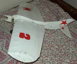
The fuselage covered with foam sheet pasted with fevicol sh. Then brown paper was used to cover the foam as is seen in the picture. it is much easier to make 2 models at a time as effort is almost the same. the brown paper was painted with enamel paint. |
 |
Be careful when painting directly on foam as this is what will happen. the foam not covered with paper just melted into a mess. i too have to learn sometimes. you can paint directly on foam if a couple of coats of fevicol is given. Use only enamel paint.
|
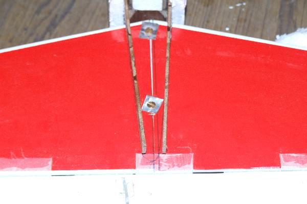 |
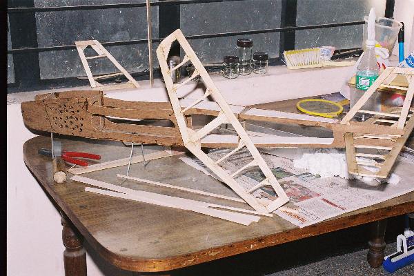
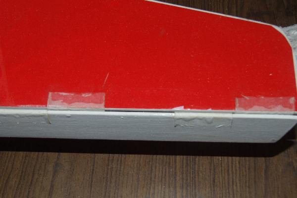
The tailplane fixed. notice the aluminium base to prevent screws biting into the balsa. elevator is joined using nylon hair ribbon from vanity shops.Use epoxy for both. monocote is used for covering the tail and fin. |
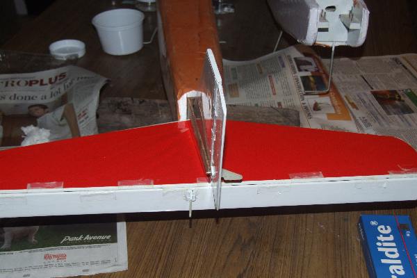 |
Fin and tail fixed. |
 |
Nose job. The engine bearear is 3 pieces of 2mm ply epoxied together and filed to shape. notice the aluminium strip screwed at the rear for strength |
 |
notice the hole in th e firewall to route the fuel tube |
 |
Elevator fixed with nylon ribbon |
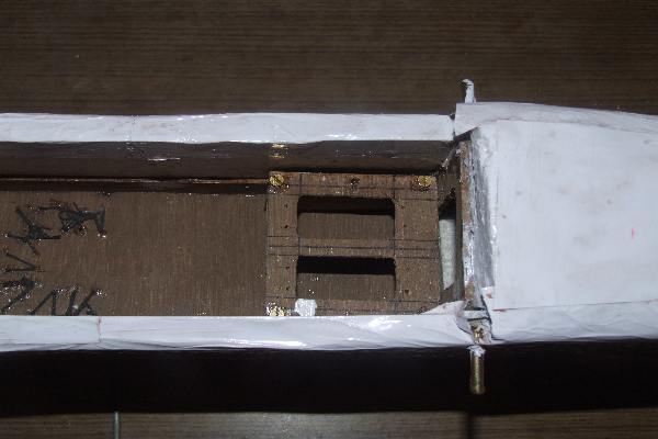 |
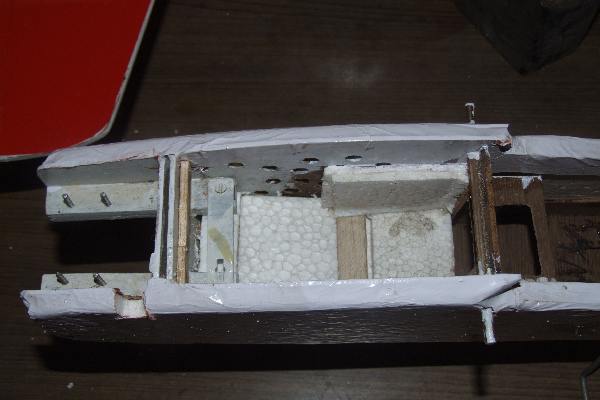
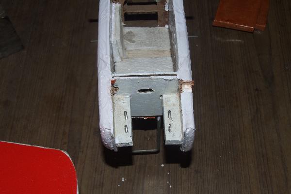
servo tray made out of plywood and fixed on wooden supports. notice the fixing of rear undercarriage using strong thread from cobbler shop. |
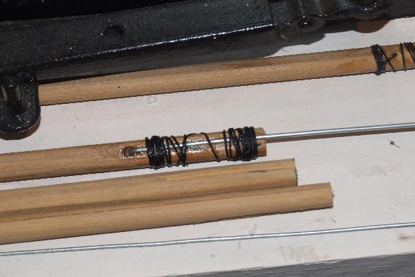 |
push rods wooden photoframe filed to shape with cycle spokes |
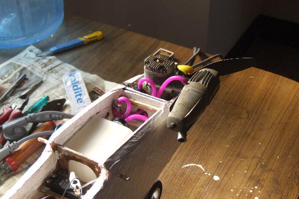 |
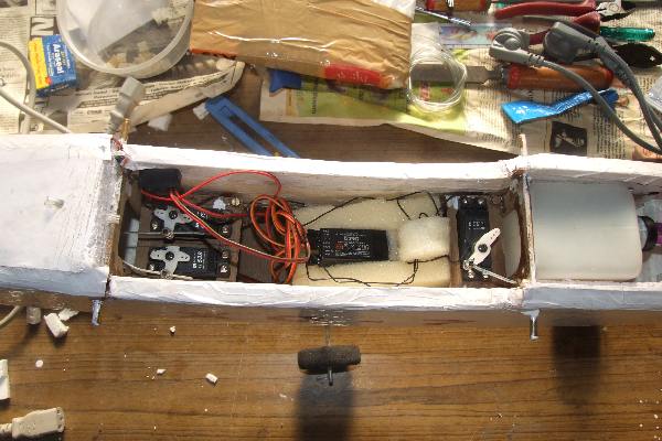
fuel tank in place along with throttle servo and engine |
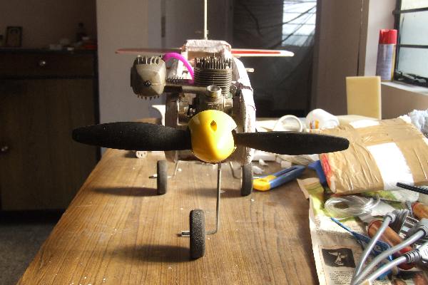 |
front view |
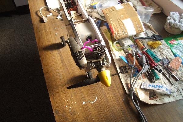 |
top view |
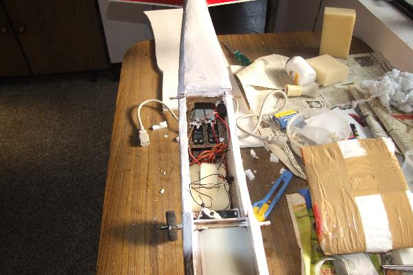 |
servo locations |
 |
|
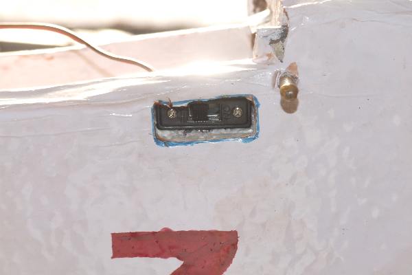 |
switch fixed by cutting a slot in the fuse side |
| i will be posting some pictures of the mainplane shortly |